
Mechanical ventilation is one of the most common ICU interventions, and understanding and accurately interpreting ventilator graphics may reduce risks and improve patient outcomes.
By Bill Pruitt, MBA, RRT, CPFT, AE-C, FAARC
Published: December 1, 2020
Mechanical ventilators provide support for patients by relieving the some or all of the work of breathing and allowing the body to heal when disease or trauma has caused normal functions to fail. This can be failure of the cardiopulmonary systems or failure of other body systems. Support can be accomplished in several ways: by helping eliminate carbon dioxide (CO2), by aiding in oxygenation, by taking over the work of breathing, and by recruiting or maintaining alveolar units.

Ventilator waveforms and loops are part of the standard monitoring package for all ICU ventilators but understanding what is being displayed can sometimes be difficult. This article will provide a look at many of the basic ventilator settings and examine how various waveforms and loops can be used to evaluate the effectiveness of mechanical ventilation in supporting the patient. The focus will be on the invasive approach to ventilation in adult patients where an artificial airway is used to provide an interface between the patient and the ventilator.
Mechanical Ventilation Basics
Breaths delivered by a mechanical ventilator are defined by four phases: the trigger phase (how the breath is initiated), the inspiratory phase (mainly dealing with the flow of gas into the lungs, or how the breath gets delivered), the cycle phase (how inspiration ends and expiration begins), and the expiratory phase (mainly dealing with the baseline pressure during the period between breaths). Many aspects of these four phases can be altered by changing settings on the ventilator and by use of waveforms the optimum settings can be achieved the best way to ventilate a patient and reduce asynchrony (this occurs when the actions of the ventilator and the actions of the patient are not working in harmony).
The trigger can occur by the patient’s inspiratory (negative) pressure reaching a set point or by the patient’s inspiratory flow reaching a set point. A third trigger is time-based on the setting for the respiratory rate. If the patient does not trigger any breaths, the ventilator will deliver breaths based on time. For example: with a rate or frequency set at 10 breaths per minute (BPM) in a patient who is not making any efforts to breath, a breath will be given every 6 seconds to achieve 10 BPM.
Inspiratory flow delivered by the ventilator is most often either a square flow pattern where flow is at a set value (LPM) and constant or a decelerating (or ramp) flow pattern where flow starts at a high level then tapers down with no preset value for peak flow.
Newer generations of ventilators can also provide a combination of fixed and variable flows in the use of dual modes such as volume-assured pressure support and pressure augmentation. The cycle phase is a function of the preset inspiratory time and preset tidal volume (or flow over time to deliver a targeted tidal volume). The baseline pressure may be zero (pressure is not elevated between breaths) or elevated above zero to a positive pressure that is held in the lungs by the action of the exhalation valve in the ventilator. When pressure is added it is called Continuous Positive Airway Pressure (CPAP) when providing noninvasive support or Positive End-Expiratory Pressure (PEEP) when providing invasive support (ie the patient has an endotracheal tube or tracheostomy tube).
Ventilator Modes
For most patients receiving invasive mechanical ventilation, either a preset tidal volume is used (called volume-controlled ventilation, VC) or a preset pressure is used (called pressure-controlled ventilation, PC) to deliver a breath. Note: inspiratory flow in VC can be selected by the operator to be either square or decelerating. Inspiratory flow in PC is always decelerating- a square flow pattern cannot be selected.
Either of these controls can be set up using a continuous mandatory ventilation (CMV) or intermittent mandatory ventilation (IMV). With the CMV approach anytime the patient triggers the ventilator to get a breath the ventilator delivers the breath by either giving the preset volume in VC or the preset pressure in PC. In CMV, no purely spontaneous breaths occur.
With the IMV approach the patient can breathe spontaneously in between the mandatory breaths then when time comes for a mandatory breath to occur the ventilator will provide the mandatory breath. Patient effort can result in variations in the spontaneous breaths. So the basic approach to give a breath can be given by four basic modes: VC-CMV, VC-IMV, PC-CMV, or PC-IMV. (See Figure 1.)
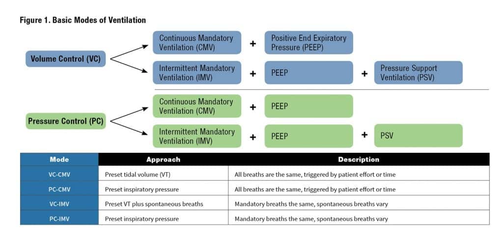
Positive end expiratory pressure (PEEP) is an available option that can be added to any of these four approaches. When PEEP is added, the patient does not exhale at the end of exhalation or back to a zero pressure baseline, but instead exhalation is ended with early so that there is a positive pressure in the airways. This increases the patient’s functional residual capacity (FRC), aids in oxygenation by keeping alveoli open and reduce a patient’s work of breathing.
Pressure support ventilation (PSV) is another option is available for either VC-IMV or PC-IMV (either with or without adding PEEP). PSV provides an extra boost of flow to all spontaneous breaths to reach a preset pressure. This helps increase the spontaneous tidal volume, helps overcome the resistance of the artificial airway, and reduces the patient’s work of breathing.
Beyond the basic modes, dual-modes are also available such as volume-assured pressure support and pressure augmentation which combines a preset volume “target” with a pressure approach to achieve the targeted volume. With changing compliance (in essence, the ease to which the lungs are inflated) the pressure used to reach the volume will adjust.
As the lungs get stiffer or less compliant (for example in worsening pneumonia or when fibrotic changes occur), volume will tend to drop at a given pressure so the ventilator will adjust the pressure upward to maintain the preset volume. As lungs get less stiff or have increasing compliance, volume will tend to increase at a given pressure so the ventilator will decrease pressure to bring the volume back toward the preset targeted volume. The adjustment in pressure due to changing compliance will occur over time and safeguards are set by the operator to avoid having pressure get too high.
Ventilator Settings
Care providers order some of the settings needed to establish mechanical ventilation. Beyond the ordered settings, respiratory therapists establish other settings to reduce asynchrony, place alarm limits (high and/or low alarm settings), use of humidification or heat and moisture exchangers, etc. Most often the provider will order the control approach, the mode, the desired tidal volume (for VC) or inspiratory pressure (for PC), the rate or frequency (f), the desired inspired oxygen level, added PEEP, and [–] if in the IMV mode added pressure support. For example, there may be an order for volume controlled continuous mandatory ventilation with a tidal volume of 400 mL, frequency of 12 BPM, 60% oxygen for each breath, and the addition of 8 cmH2O PEEP. In an abbreviated form this would be:
VC-CMV, VT 400 mL, f-12, FiO2 .60, + 8 cmH2O PEEP
Here is an example of an order for pressure-controlled intermittent mandatory ventilation with a peak inspiratory pressure of 20 cmH2O, frequency of 14 BPM, 40% oxygen for each breath, the addition of 5 cmH2O PEEP and 5 cmH2O pressure support:
PC-IMV, PIP 20, f-14, FiO2 .40, + 5 cmH2O PEEP, +5 PS
All other settings necessary for safe and effective ventilation are determined by the respiratory therapist involved with the patient’s care.
Ventilator Waveforms: Scalars
Scalars provide a basic look at changes in the variables of flow, pressure, and volume over time. They can be displayed alone or in combination (either 2 or all 3) on the ventilator screen. During the time of a breath, all 3 of these variable occur simultaneously. With selection of a slow “sweep” speed, several breaths can be displayed on the screen and trends in ventilation can be examined over time. A fast sweep speed will show much fewer breaths (perhaps even just one breath) and more details can be examined for the breath delivery. Many ventilators will give the operator an option to “freeze” the display and look at the flow, pressure, and/or time scalars without having the ventilator update and change the screen for subsequent breaths. Otherwise, the screen will update the view on the screen over time.
For a more detailed view and explanation of ventilator waveforms, see Examples 1-8 below.
Conclusion
Ventilator graphics in the form of scalars and loops allow for a visual assessment of the patient-ventilator system and can help uncover problems that should be addressed. Spending time studying examples such as those shown in this article can help sharpen the skills needed to recognize problems. Adjustments to the variables such as sensitivity, inspiratory flow and volume, pressure support, PEEP, breath rate, and other settings can reduce work of breathing, decrease possible damage caused by mechanical ventilation, and make the patient more comfortable.
This article has touched on some of the basics of ventilation an ventilator waveforms; there are excellent textbooks, web-based teaching materials, and publications from the ventilator manufacturers that go deeper in showing what graphics can do to help effectively and safely ventilate a patient.
RT
Bill Pruitt, RRT, CPFT, AE-C, FAARC is a senior instructor and director of clinical education in the department of Cardiorespiratory Sciences, College of Allied Health Sciences, at the University of South Alabama in Mobile. He is also currently an elected member of the Board of Directors for the National Asthma Educator Certification Board (NAECB). For more information, contact [email protected].
Sources for More Information
- Cairo, JM. (2016) Pilbeam’s Mechanical Ventilation, Physiological and Clinical applications. 6th ed. Ch 9.
- Gentile MA. Cycling of the mechanical ventilator breath. Respiratory Care. 2011 Jan 1;56(1):52-60.
- MacIntyre NR. Patient-ventilator interactions: optimizing conventional ventilation modes. Respiratory Care. 2011 Jan 1;56(1):73-84.
Examples
Example 1. Scalars for Volume-Controlled Continuous Mandatory Ventilation (VC-CMV) with PEEP.
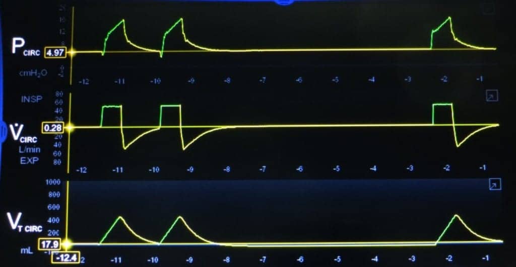
Inspiration is shown in green, exhalation is shown in yellow in the 3 scalars. A square wave inspiratory flow is shown on the middle scalar. Inspiration is above the baseline and expiration is below. Three breaths are displayed. The first two breaths are triggered by the patient’s inspiratory effort and can be seen in the pressure scalar (on the top) indicated by letter A. The slight drop from the baseline shows the patient effort. The third breath occurs after a period of no patient efforts and is time triggered, indicated by letter B. The settings are VC-CMV, 450 mL, f – 6 BPM, (FiO2 not shown on this illustration) +5 cmH2O PEEP. The bottom scalar shows the tidal volume. In VC-CMV all patient efforts that are sensed by the ventilator will trigger a set tidal volume for delivery to the patient and any time-triggered breaths will also result in delivery of a set tidal volume.
Example 2. Scalars for VC-CMV with PEEP, decelerating or ramp flow.

A decelerating (ramp) wave inspiratory flow is shown on the middle scalar. Inspiration is above the baseline and expiration is below. Three breaths are displayed. The first two breaths are triggered by the patient’s inspiratory effort and can be seen in the pressure scalar (on the top) indicated by letter A. The slight drop from the baseline shows the patient effort. The third breath occurs after a period of no patient efforts and is time-triggered, indicated by letter B. The settings are VC-CMV, 450 mL, f-6 BPM, (FiO2 not shown on this illustration) +5 cmH2O PEEP. The bottom scalar shows the tidal volume. In VC-CMV all patient efforts that are sensed by the ventilator will trigger a set tidal volume for delivery to the patient and any time-triggered breaths will also result in delivery of a set tidal volume.
Example 3. Prolonged exhalation.

This example shows a prolonged expiratory time as might be seen in a patient with COPD or having severe bronchospasm. Observe how long it takes for the exhalation to end, especially in the VT waveform. The first breath is time-triggered, the second is patient-triggered. The prolonged exhalation could be made worse by secretions in the airways that interfere with exhalation. Should this patient have a higher respiratory rate there might not be enough time to exhale between breaths and air-trapping or auto-PEEP could occur. Some possible ways to correct this would be to shorten inspiratory time setting, provide medications for bronchodilation, suctioning secretions, decreasing the set breath rate, or replacing a smaller ET tube with a larger one.
Example 4. Spontaneous Breathing in VC-IMV with PEEP and no PSV.

This example shows total of 6 breaths, all triggered by the patient’s effort (look for the slight drops from the baseline pressure prior to each breath). PEEP is set at 5 cmH2O. Breaths 1, 3, 4, and 5 are spontaneous breaths with a tidal volume of about 100-150 mL. The intermittent mandatory breaths are number 2 and 6, which are delivered with a decelerating flow setting and a set tidal volume of 450 mL.
Example 5. VC-SIMV with PEEP and Pressure Support Ventilation of 5 cmH2O.

This example shows three patient-triggered breaths. PEEP is set at 5 cmH2O. Breaths 1 and 3 are spontaneous breaths with 5 cmH2O pressure support added to boost the spontaneous tidal volume to about 400 mL. Breath 2 is an intermittent mandatory breath delivered with a square flow and a tidal volume of 450 mL and reaches a peak inspiratory pressure of 16-17 PEEP cmH2O.
Example 6. Patient effort not being sensed by the ventilator.

This example shows one time-triggered breath (the first) and five attempts to breathe by the patient (shown in the pressure scalar). Only one breath from the five efforts is actually delivered (the final breath). The mandatory breaths have a square flow and a tidal volume of 450 mL and PIP reaches about 16-17 cmH2O. PEEP is set at 5 cmH2O. This asynchrony can be very uncomfortable to the patient and increases their work of breathing. The sensitivity setting needs to be adjusted to a lower number so that the patient efforts will result in a breath being delivered.
Example 7. Normal Pressure-Volume loop and Flow-Volume loops.

This example shows a normal Pressure-Volume loop (P-V) in the top graphic and a normal Flow-Volume loop in the bottom graphic. Inspiration is in green, exhalation is in yellow. The settings on the ventilator are VT 450 mL, square flow waveform, and 5 cmH2O PEEP. These loops were generated by ventilating a test lung.
Example 8. Pressure-Volume loop and Flow-Volume loops with overdistension.

This example shows an overdistension of the lung due to a tidal volume that is too large for the patient and a pressure overshoot. The tidal volume is set at 680 mL and the overdistension is seen in the P-V loop at close to the end of inspiration. There is a rapid increase in pressure with much less increase in volume, resulting in what is often called a “bird’s beak” appearance in the graphic. This can be harmful to the lungs and cause damage due to barotrauma (due to the high peak inspiratory pressure) and volutrauma (due to the large tidal volume). This can be corrected by reducing the tidal volume delivered to the lungs.


When a vent keeps beeping saying circuit disconnected what do you do?
Follow the circuit or tubing from the vent to the patient, tightening the connections and looking for a leak or hole. Some circuits have holes for temp probes and if they’re not plugged it can show a circuit disconnect. If your patient has a trach and the cuff is deflated that may show a circuit disconnect. Finally, if the patient is wearing a mask and it has a significant leak then it may also be the cause for a circuit disconnect alarm beeping.